|
|
|


A Simple Transmitter
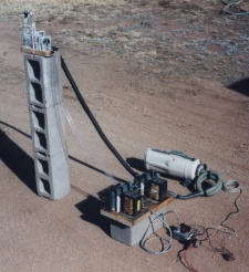
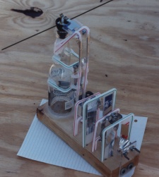
How simple can a transmitter be ? Glue a few straws together, wrap them with aluminum foil, snip up some soda bottles and aluminum cans and then glue it all to a block of wood and a beer bottle. Sounds like a plan.....
In reality, it takes a lot of time to do this. Precision construction is important. Handling the foil is difficult. What you save in material costs is made up for by the labor required to collect, clean and prepare the bottles and cans. In return for these troubles you get a sense of how the circuit does what it does. During the time that it takes to construct it you visualize what you cannot see, the electricity flowing into it and emerging as radio waves. That's why the design has only one non linear component, the spark gap. It is easier to visualize the operation with it instead of with transistors.
There are only four types of electronic component used in this design. They are coils, capacitors, a spark gap and two antenna. The actual transmitter is only the antennas and the output capacitor connected to the spark gap. The other parts cause a voltage increase due to resonant effects. Each loop of the circuit has current flows that engage adjacent loops like invisible gears. Because the impedance of each loop increases as you get closer to the antenna a voltage increase occurs at the antenna. The trade off caused by this circuit is that large amounts of input current are required and most of that energy is turned to heat by the circuit.
The original design was carefully computed to produce an output on the lower UHF band so that the TV could be used as test equipment. During construction it became clear that the computations did not include many other factors which will effect the final frequency. If the width of the inductor coil ribbon varies by an amount equal to the thickness of the foil the value of the inductor changes. If the exact position of the foil on the straw changes the value changes again. Every little crinkle and bend in the ribbon will count as a stray inductance.
The capacitors have their own additions to chaos. The exact thickness of each plate varies from the intended thickness due to ripples in the metal and to clamping pressure used during construction. The resonant line is folded up to make the size of this project convenient. There will be significant capacitive additions between components. The alternative is to make the circuit in the shape of a long line and mount it on a 4 foot long wood base.
The connections add even more error to the desired result. They will function as resistors. That changes the frequency again. The threads of the screws and the washers on them will both function as inductors. If that becomes important it can be controlled by cutting a groove along the screw threads and by cutting a gap in the washers circle.
The electrical plug used for the antenna, capacitor and spark gap mounting has a 90 degree twist in each side. That will add a base inductor effect to the antenna. It may be negligible or it may not be.
To make a long story short, there are as many unintended components as there are intended ones. It will be interesting to find out what the final frequency is. The following pages cover the design and the construction of each of the components. Use the back arrow of your browser to return here. The actual testing will be covered in another edition of this web page project.