|
|
|
The capacitors are made by gluing pieces of plastic soda bottles and aluminum cans together. To make a long story short; cut the pieces, glue them together, clean & trim them and drill holes in the legs. It takes a fair amount of time to get this done. These will be somewhat low grade, low power capacitors. They may be made adjustable by folding an outside plate that wraps around the capacitor. That flying plate would then be slipped over the capacitor and secured by scotch tape at each setting.
The power supply capacitors are made from common window glass with aluminum cans for plates. They are stacked with dabs of glue and wrapped with electrical tape to hold them together. Their purpose is to limit current flow and thereby prevent the transformers from burning out. The ones shown should pass about 50 % of the available current. They could be made two to four times larger to pass the maximum amount of continuous current. They could be made even larger (or eliminated) for pulse operation. Do not substitute regular electrolytic capacitors for these, particularly the ones that were used with the transformer in the microwave oven. They would probably explode violently if you do.
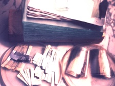
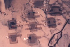
Left side- All the pieces Right side- The plastic capacitors
To begin construction of the plastic capacitors collect a dozen plastic soda bottles and another dozen aluminum cans. Cut them open with a pair of scissors so as to get the largest flat piece of material from each. Wash and dry them. Straighten the aluminum cans out by sliding them around a piece of a broom stick. Make them reasonablely flat.
It is much more practical to mark the aluminum using a felt tip ink pen and ruler than it is to make taped on paper template. Mark X pieces as shown on the pattern picture. Cut out all of the pieces. Smooth and flatten each piece. Use #150 sandpaper on all edges from both sides to remove small burrs. Sand both sides of the legs to allow a good electrical contact. Put a wrap of masking tape on each leg. The edge of the tape should be 1/4" from the plate area. It purpose is to prevent the legs from being glued together.
The soda bottle plastic is simply cut into strips. There are two sizes to make, 1" wide and 1 ½"wide. Avoid using plastic where there is a ridge, a crease or pieces of the label. Mark with felt tip pen and cut with scissors.

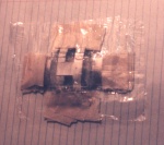
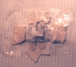
Views of capacitors after stacking and before clamping
The capacitors are assembled using pieces of glass as work surfaces. There is a small piece of plastic wrap on the bottom of each stack to prevent the capacitor from sticking to the glass. The parts are then stacked and taped down. The finished stack is covered with a larger piece of plastic wrap. A small square of glass (approximately 1 ½" square) is then placed over the capacitor plate area to distribute the clamping pressure.
The smaller capacitors may be made on the same piece of glass. The clamping pressure will distribute itself evenly. The larger capacitors are done separately because they are bigger and wobblier stacks. The clamping pressure is applied by placing iron plates on top of the stacks and then adding additional weights on top of that. Rigid wood blocks and any convenient weights may be used. A fairly heavy pressure is used. Do it on a solid flat surface or the glass work surface may break.
They need to dry for about three days before removing the pressure. Even then the glue in the center is still wet. Remove all of the masking tape pieces carefully. Trim the excess glue away using a razor blade knife. Remove the masking tape on the legs with a razor blade knife. The may be some adhesive residue on the leg surfaces. Remove that using sandpaper. Only the contact areas at the tip of each leg have to be clean.
Drill the holes in the tips of the legs by clamping the legs between pieces of wood clothes pin. Use a sharp 1/8" drill. This is shown below as it is being done to the power supply capacitors. The pieces of wood clothes pin do not have to be cut up as shown. You may use each piece one time and then reassemble the clothes pins with a new hole in the tips of their handles.
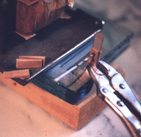
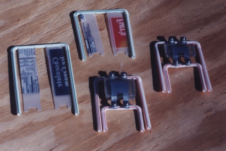
Left Side- Only the drill bit is shown as it hangs in the drilled hole. Right Side- Capacitors in holder frames shown next to coil forms
Let the glue dry for a few more days before trimming the excess plastic off. Trim the excess off at about 3/8" from the edge of the plates. If a pair of shears is used the plastic will buckle and separate. A mototool cutoff disk may work well. These were done using a hot piece of coat hanger to melt through. The coat hanger tool is shown in the first picture of the completed capacitors. It was a little bit short and got hot to hold while using. The results were a bit messy. The edges being cut tended to mushroom and the bottom side had a melted mess hanging from it, but the plates did not separate. If you do it this way practice on the area that gets trimmed off. You'll need to get the coat hanger red hot but not too hot. The thicker capacitors will have to have several attempts to make a complete cut. Trim as needed with razor knife.
The power supply capacitors are a bit easier to make. After preparing the plates the next step is to drill the holes in the legs. To do this, stack them together and drill them as shown in the previous picture. The hole is drilled at the tip of the shortest leg. The legs are then trimmed where the hole is. Trim a round end. Number the plates so that they may be assembled correctly.
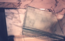
Put four tiny marks on each piece of glass.
Prepare X pieces of glass 5" x 8". Sand the edges lightly with extra course sand paper to remove sharp edges. Place four tiny marks where the edges of the plates will be to help stack them straight during assembly. A piece of 1/4" mirror is used as the work surface because it makes alignment easier during assembly. If you can get double strength glass, make four pieces of it to use as the outside pieces. You'll see why later.
To assemble these capacitors simply stack them together using visual alignment. For each plate put a thick fingerprint of glue near each corner of the plate. This is to prevent shifting. The assembling needs to be done at the edge of a counter top because ½ of the legs will extend below the work surface.
When the stack is assembled place heavy weights on top of it for clamping pressure. These were both placed at the bottom of a stack of three microwave transformers. Let it dry for three days. Remove the weights and place three bands of electrical tape around each capacitor to hold them together. Each band should be about 5 to 7 wraps. Wrap the tape firmly but not too tight.
The next step is to make legs for the capacitors. Cut four pieces of ½" PVC pipe about 4 ½" long for each capacitor. The angle cut end is optional. Put a small bead of silicon glue on the plastic pipe where it will contact the capacitor. Place two of the legs on each capacitor and put the entire assembly in a square corner of a counter top. This causes the legs to turn out square and even. The capacitor is resting on two cassette tapes. When dry place the second two legs on in a similar way. This time the capacitor will be standing on the two legs it has and resting on the two cassette tapes. See picture.
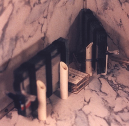
Left Side- Glueing the legs on. Right Side- Finishing the legs
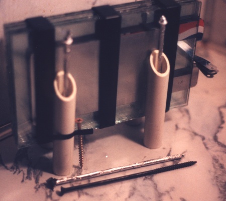
To allow the capacitor to be screwed down the ends of the legs are filled with silicon glue. A hole through the glue is made by putting a long screw wrapped with foil into the glue. The picture shows one leg with a screw taped to it. The piece of tape shows how much glue is inside the leg. The screw stuck to the tape is the size that will be used to hold the capacitor to the wood base. A small washer is put on the screw and the screw does not get over tightened.
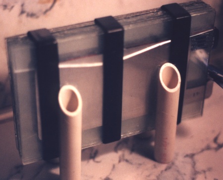
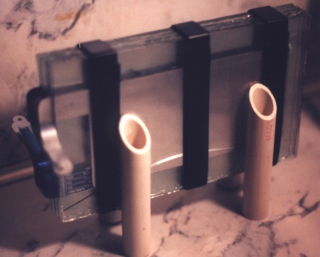
Don't put too much tape on.
These capacitors were made using 10 wraps of tape to hold them together. The first crack appeared the next day. The second crack appeared 3 days later. A third crack appeared a week later. These were produced as winter began. The room temperature at night was colder each day. Only the outside pieces of glass cracked and so they are still fit to use. The shape of the cracks indicates that the middle band was too tight. The circuit design has these two capacitors in series. If one of them breaks an internal plate and allows arcing to occur the other one will still limit the current at a higher rate. Fortunately only one of the capacitors did this.