|
|
|
A transmition line is usually something that connects the transmitter to the antenna. Its length has to be a multiple of the ½ wavelength being used for it to function properly. For this transmitter the RF energy originates at the spark gap which is located at the antenna. However, because the 'transmitter' is separate from the power supply a connecting line is needed between the two. The power supply capacitors are the first element of the series resonant line. The addition of wires to connect the power supply to the 'transmitter' will add an inductance or a capacitance to the resonant line unless the length of the line is of an exact multiple of the ½ wavelength being used.
When the transmition line is of the correct length it will function as a resonant element just as the antenna does. Because this transmitter is more like a bell that rings when hit by the power draw of the spark gap, anything that can be tuned should be. The length from the edge of the power supply capacitor plates to the edge of the first coils on the 'transmitter' should be an exact multiple of the ½ wavelength.
Normally that is not too difficult because you usually know what frequency you are using. In the case of this transmitter you do not know that. The exact values of the capacitors are not known because of capacitive coupling between components. The exact value of the coils are not know because they are of such an unusual design. The connections will add an unknown resistance to the circuit also. The final frequency produced may or may not be close to the intended frequency.
Therefore, at this point in time, any length will do. Once the output end of the resonant line has been tuned the length of the transmition line may be adjusted to improve the 'Q' of the circuit. The only major concern is to make a connecting line that is not very capacitive. To do that the line is made using skinny wires that are spaced far apart.

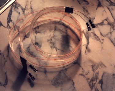
The transmition line
This transmition line is made of #20 enameled wire between two pieces of packaging tape. The tape is 1 7/8" wide and the space between the wires is about 1 1/16". It could have been made using regular scotch tape to secure each wire to a strip of paper or plastic. The connections at the ends are regular spade lug connectors. They are soldered on because the wire is too small to crimp onto.
For this wire size and spacing the transmition line impedance would normally be about 500 Ohms. The tape will add a tiny amount of capacitive media to the line causing its impedance to be a bit lower.