|
|
|
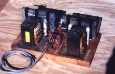
The power supply is made from two microwave oven transformers. It has two current limiting capacitors to prevent the transformers from burning out. That's all there is to it. The transformers came from commercial grade ovens. Their output voltage is 4 KV. A regular retail oven transformer has 2 KV as its output voltage. Any transformer that can make a high enough voltage to cross the spark gap may be used.
The transformer outputs are wired back to back so that the voltages add together. The cold side of the output is the side of the winding closest to the core. For these transformers there is a wire to make that connection with. For regular retail oven transformers the cold side is connected to the core. To use them the cores get connected together.
The power input windings are connected in parallel. The polarity is reversed for one of them so that the output voltages produced are '+' and '-' for each cycle. If not connected this way the two outputs stay at the same polarity with no voltage developed between them. There is usually a third winding to provide power to the filament of the klystron. These wires usually have extra insulation added to them. They only produce a few volts and may be clipped off.


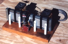
Front and back views of power supply
The microwave ovens usually have a small connection board in the power supply area. Remove all components from it and use it for a wiring board. If soldered parts are removed use #150 sandpaper to remove solder from the connection tabs. The power line has a strain relief made by wrapping coat hanger around the line. The coat hanger then has two small loops added for screw holes to secure the line to the wood base.

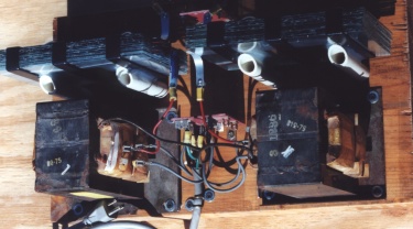
Top View
The exact layout of components on the wood base is not too important. It is a good idea to keep high voltage wires short and in the same general area instead of strung out all around the supply. There is no on/off switch for safety reasons. Each time you reach towards the power supply you increase your chances of getting electrocuted by it. The power is controlled at the plug end of the power line by a relay instead.
The capacitors allow three power levels to be chosen depending on how they are wired. With one capacitor on each line the lowest power level is selected. If either capacitor is bypassed by connecting its terminals together the medium power level is selected. If both capacitors are wired in parallel and put in series with either output line the high power setting is selected.
To get even more power out of the supply it may be run from a car alternator. At the higher frequency of the alternator the capacitors offer a lower resistance. The alternator would have to be driven by a car engine to provide enough mechanical power to turn it. The voltage applied to the rotor would have to come from two or three car batteries. The alternator functions like a 4:1 step up transformer. Using two 12 volt batteries will produce about 96 Volts. Three batteries would produce about 144 Volts. Either way it would only be for pulse operation because the rotor will burn up for continuous operation.