|
|
|
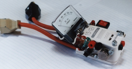
External part mountings using epoxy.

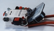
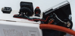
Internal views.
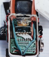
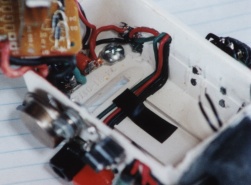

This started out as a simple idea. Glue a few parts to a power supply and wire them together. As construction proceeded more parts got added to the design. Looking back, far more trouble went into getting the parts to fit together than anything else. There just wasn't enough space. The wires are recessed inside grooves cut into the plastic with a mototool.
The circuit itself is a simple voltage follower power transistor using a small power supply as its reference voltage. The power that comes out of it is provided by an external car battery. The car battery provides a low impedance source. That means that it will be able to power the alternators rotor and not get weak under heavy loads. The basic design of the circuit is primitive. That is chosen for durability. The experiments that it is intended for will probably have short circuits, overloads, arcing and other unintended problems. A more fragile power supply would burn out every time. At the very least it is hoped that this one may be repairable after accidents happen.
Neither the switches nor the lights are what you might expect them to be. The red 'Power OK' lights are similar to 'On' lights. They show when the 120 VAC power is within range to operate the neon light bulb and if the 12 volt supply is still active . They tell of the condition of the supply voltages and not of the on/off status of the regulator. The yellow LED for the 'Output Enable' switch is similar to an on/off light. The difference is that the switch merely enables or disables the output and does not actually turn the power supply on or off. The green output indicator will not show low voltage outputs. It will show if the transistor is overloaded.
This may seem like an odd way to design it until you consider the application it is designed for. For power plant applications there will be no 120 VAC. Instead there will be a varying voltage from the alternator that provides the input power. For other experiments there will be no car battery. Once again the alternator will provide that supply voltage. These types of circuit setups are unstable and unpredictable. The lights provide more information about the external circuits than about the regulator.
The stereo jack is for advanced experiments. It allows external modulation signals to be added to final output voltage. There are several uses for this. For power plant circuits it allows corrective feedback to be added to the rotor drive voltage. For general tests it allows for a remote control switch to be used. The PowerMouse may be used although the lights won't work. For the transmitter tests it allows an input signal to modulate the transmitter output at low frequencies.
Four small signal transistors may be wired in parallel and added to the power transistor for more precision control of the output. The original circuit does not include this feature because the regulator will very probably get burned up a time or two during initial tests. They would just be four more parts to replace until better operating procedures are established. The two terminal posts on the front corners are ground connection test points. One is for generator ground the other is for supply line ground.