|
|
|
Now that you have some RF energy you need to let it out of the circuit. If you don't it will travel as far as it can and then return to where it came from. That is called a standing wave. It accumulates until it gets back into the power supply. That causes it to be dissipated as heat. It usually causes circuits to malfunction as well because RF energy is a free energy source to just about everything. If RF energy is trapped in a tank it is good to have standing waves. That is how a microwave oven concentrates its RF energy to high power levels. In a similar way a waveguide makes a strong narrow beam with the same amount of energy that would also make a weak omni directional radiated wave.
There are many antenna array combinations. Most of them are combinations of basic ½ wave dipoles or 1/4 wave monopole sections with phasing or positioning adjustments. Those all work on the same principle. Each dipole or 1/4 wave section has a maximum amount of power it can radiate per unit of source voltage. To combine antennas for direction or strength it appears that you need to know how combinations affect each other. They don't. They work as separate elements. The only requirement is that each radiating element be phased or spaced so that it causes its RF energy to arrive at the target all in the same phase. They are like separate spotlights shining at the same target. If out of phase they cause cancellation at target. A canceled RF waves energy merges itself to adjacent non canceled RF waves. Redirection of a fringe wave is the result.
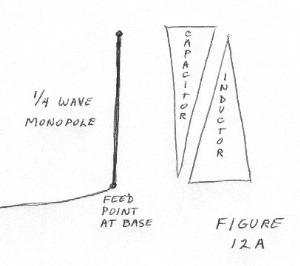
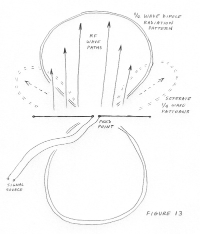
The previous paragraph stated that separate RF radiations do not affect each other. That is true after they leave the antenna element. Just before that happens it is still possible for antenna elements to affect which direction the final RF wave emerges at. A 1/4 wave monopole antenna radiates in a cone shape. See figure 12a. When two of them are placed back to back ( forming a ½ wave dipole ) the magnetic and electric fields have one last chance to pull on each other. The result is the ring shape of the pattern of the ½ wave dipole. See figure 13. A similar effect occurs for a long wire antenna. The fields compress against each other and cause a long lobed directional pattern for transmition. The same effect in reverse causes voltage multiplication when used for receiving. See figure 14.
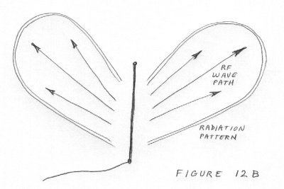
There are two major ways for RF energy to jump off the antenna wire. The most common is the 45 degree lobes of a 1/4 wave antenna. This includes the ring shape of a dipole, which is merely two 1/4 wave antennas back to back. See figure 12c. Once the RF energy has been created at the transmitters final control element, the energy waves have to travel to the antenna. They go in the direction of lower impedances. They cling to the wire and will dissipate energy to the ground or to the opposing phase it if exists. When they get to the antenna they need to have specific values of source impedance to match the antenna and cause lower SWR. To bypass matching troubles the antenna is frequently connected directly to the RF output source if possible.
The circuit from the RF output point ( the switch ) to the antenna is considered the RF circuit. The RF energy travels only in this area. It hopefully goes to the antenna and exits. The other things it could do is to get dissipated as heat or reflected back to the source causing a greater SWR that the minimal 1:1 ideal ratio. The RF energy goes toward lower impedances directions. A signal traveling in a 50 ohm circuit will go to a 48 ohm circuit easily. The final impedance is the antenna. The antenna is both a inductor and a capacitor. See figure 12b. Its exact shape and size control many adjustable options in its design. Just about anything will work one way or another.
SWR is an acronym for Standing Wave Ratio. The transmitter uses AC to create RF. If all of the RF energy would leave at the antenna there wouldn't be a problem. Only part of it leaves. A full sized image of itself stays because RF energy seeks to spread itself everywhere including where it came from. If the returning RF image is equal in size to the original AC signal the condition as referred to as a 1:1 ratio of standing waves. The transmitter merely reflects it back out again because the returning RF image should be in phase with the transmitters AC output. If the RF image is out of phase it does reflect back into the system. It keeps its energy instead of giving it back to the transmitter. It then adds together with other stray RF signals until it is much bigger than the original transmitter output. Then it is a major problem. First of all it has failed to radiate as intended. Second is that the energy accumulation that it will become burns up the transmitter and/or the cables to the antenna. Even though the standing wave can become many times greater than the transmitters output power it cannot leave at the antenna because it is not in its voltage phase when it gets to the base of the antenna. The more time it return to the antenna to try to radiate, the farther out of phase it becomes. It is trapped and accumulating in the output circuit.
When a RF signal arrives at the base of an antenna it sees the antenna as a capacitance to go charge up with its energy. The RF signal is in the static charge ( voltage ) phase of its existence. Whatever the charge the antenna has, the new RF static charge seeks to go replace it. As it does so two things happen. The first is that the RF energy goes into its next phase of magnetic energy on the base of the antenna. The second is that the tip of the antenna starts to become charged up to the new static charge level from the RF static charge phase..
As the RF energy goes into its magnetic phase it uses some of its energy to create a transconductance corridor at that new location. That energy used will later become the radiated energy. The capacitance of the tip is decreasing rapidly in value as it fills up. Unlike a regular capacitor it has only one plate. As that plate fills its capacitive ability drops faster that a two plate capacitor. Because of that the voltage of the tip looks less approachable to the RF energy at the base of the antenna. The energy begins to get reflected back to become the standing wave. As the energy turns away from the antenna the transconductance corridor begins to collapse. The excess energy from the magnetic charge that was using the corridor finds itself inside a bubble of low impedance which is ceasing to exist. That energy becomes free of the antenna and emerges in the static charge phase of the radiated RF wave. The collapsing magnetic fields give it the exit path of 45 degrees. That is the first 25 % of radiation.
If the RF source is a push-pull type the following RF wave will actively cancel out the previous one as it causes a negative voltage at the base of the antenna. That negative voltage causes the charged up tip of the antenna to be usable as a fully discharged antenna to the new polarity of RF voltage. Either way the final effect is still similar to creating waves on a pond.
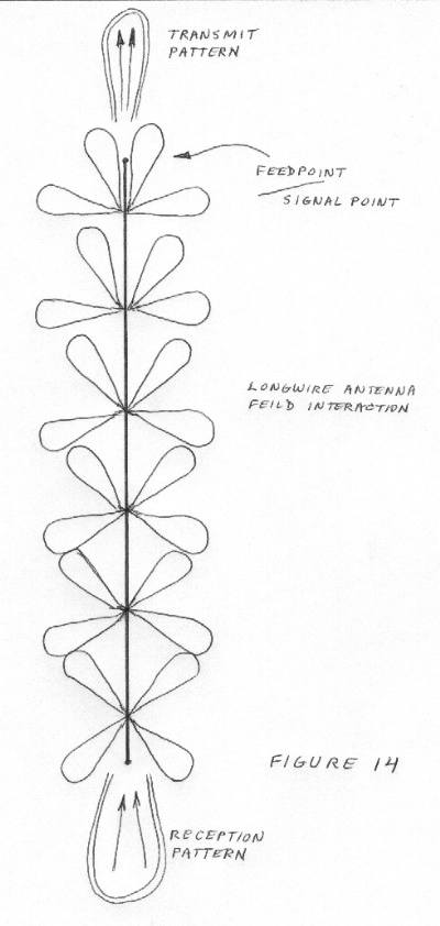
The second major way for RF energy to leave an antenna is on a long wire antenna. When RF energy travels it tends to radiate itself just about everywhere using partial wavelength 'apertures'. It is stopped from radiating by using balanced transmition lines or shielded coax lines. A long wire antenna is many wavelengths long. It radiates in the usual way all along its length. RF energy is emergent all along the wire but its fields compress against each other. That happens because the RF energy is not quite free of the antenna wire when it emerges. The magnetic interaction is caused by the antenna wires magnetic fields. They give shape to the magnetic field of the RF energy which then shapes the RF static charge path. The static charge path is what guides the RF wave to its destination. See figure 14.
The RF energy travels slower in the wire that it does in free space. The wavelength in the wire is slightly shorter ( about 3 % ) than in free space. The RF energy has to emerge where the wire allows it to. That spacing is closer than the RF free space wave would choose. The result is that the free space wave gets 'compressed' along the length of the wire. That compression occurs as the last effect that the wire can cause on the RF wave. It is caused in the magnetic phases. Those phases are opposed to each adjacent phase. The result is similar to a stack of opposing ring magnets on a dowel rod. The emerging magnetic energy is compressed along the length of the wire. The emerging static charge wave angle is about 5 to 10 degrees from the wire. For transmitting, the magnetic compression at the back of the antenna causes the RF energy to get directed away from the feed point end at the front end. For receiving, the compression at the signal tap point at the back of the antenna causes a voltage summation of the received signal to occur
Because RF waves will add together at the target without a problem it is possible to combine many antennas in a very simple way called the Rhombic Antenna. It is a square in shape. Each side of it several wavelengths long. The RF energy that comes out of each wavelength section is radiated at an angle of 45 degrees to the wire. Half of all radiated lobes are in phase and pointed in the same direction. That causes the rhombic antenna to be highly directional. The side lobes cancel each other out. See figure 15. Only the forward RF waves are shown ( as arrows ). The back side radiation is identical. The feed point for transmitting is at the front of the antenna. The signal point for receiving is at the back of the antenna. The antenna is bidirectional as far as front and back go. The terms front and back do apply to a small extent.
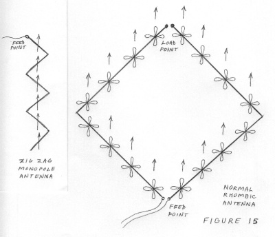
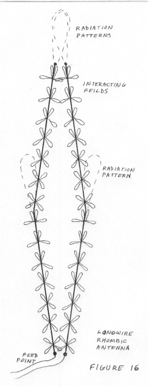
It should be possible to combine long wire antennas into a rhombic antenna. The angles between each wire and the final direction would be 5-10 degrees instead of 45 degrees. See figure 16. Since the rhombic antenna and the long wire antenna are both directional the resulting combination should be even more so. A high SWR and a low efficiency are to be expected. A simple 'Y' combination may be as far as you can go with this idea. The antenna would then be made of two long wire antennas at a 5-10 degree angle from the antennas direction. A monopole rhombic should be feasible. It would be a single wire of many wavelengths. At any point between wavelengths the antenna may turn 90 degrees. It would appear as a very long zig zag wire. See Figure 15.
So that's how you turn DC to RF.........