|
|
|
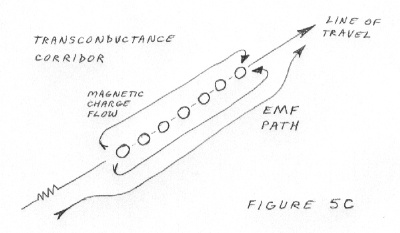
There is one final concept for you to grasp before we launch any RF waves from the antenna. It is transconductance. To put it simply, if a piece of magnetic material is near a wire the resistance of that wire goes down. It does so because the magnetic corridor from the wire finds a lower magnetic impedance path to use in the metal than that of free space. This is true even for DC current in a wire. The resistance of the wire actually goes down because of a nearby piece of metal.
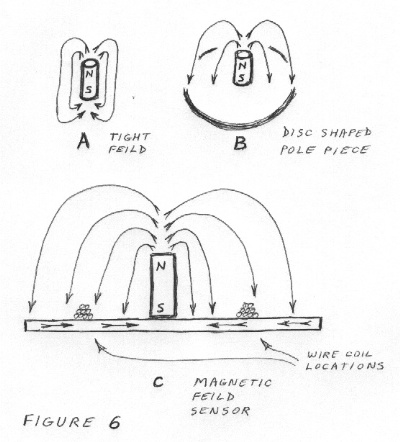
This principle is hard to accept and believe until you build a impedance pickup amplifier and prove it for your self. What is a impedance pickup amplifier ? It is an amplifier that uses a magnetic pickup for its input device. Look at the picture of the magnetic pickup in figure 6. In figure 6a you see a plain magnet and its field lines. In figure 6b you see the same magnet with a pole piece. The pole piece stretches out the magnetic field from the magnet because it is a low impedance path for magnetic energy. In 6c you see the location of the wire loop in the magnetic field.

Notice that the wires position is in the middle of the field. It is not wrapped around the magnet nor is it at the edge of the pole piece. The reason is because the wires receive EMF charge when something causes a magnetic line to try to cross the wire. A piece of metal will cause the field to seek it. A magnetic line cannot cross a conductor. It breaks at that point and gives up its energy into the wire as EMF. The EMF 'senses' the circuit impedance and transforms itself into appropriate voltage and current levels. The pole piece has opened the field up for easier access by the wire. The strongest location of the field is not the best place the put the pickup loop of wire. The midpoint of the opened field is.
That principle is the motor/generator effect at work. It is not transconductance. When a piece of metal is brought near the pickup the output voltage from the amplifier swings positive for a moment and then returns to mid voltage. When the piece of metal is removed the amplifier voltage swings negative and then returns to mid voltage. That is how the circuit was intended to serve its purpose as a metal detector. An additional discovery was made after building it. When the metal was merely setting on the pickup the output voltage was a tiny bit higher than when it was removed. That was the transconductance principle at work.

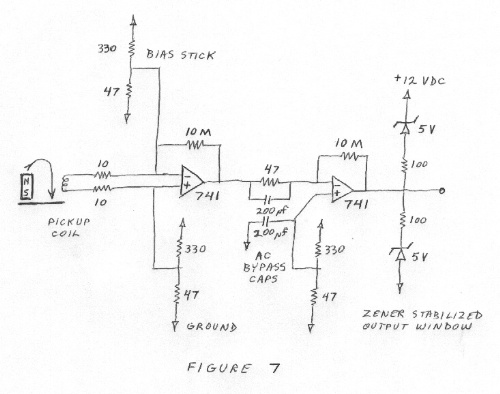
Figure 7 shows the schematic of a inductive pickup instrumentation amplifier. The amplifiers are common 741 op amps. Its two inputs were setup to sense the tiniest current at the lowest possible input impedance. Because it is nearly impossible to make a perfect balancing of the two inputs there is a slight current going through the pickup coil caused by the amplifier. The amplifier functions as a resistance sensor to that extent. When the resistance of the pickup coil changes the amplifier shows it. If the amplifier is on the upper side of balanced it shows a tiny increase in voltage when a stationary piece of metal is near the pickup coil. If the amplifier is on the lower side of balanced it shows a slight decrease of output voltage. For both conditions the amplifier still gives a great positive response to metal approaching the pickup and a great negative response for metal leaving the pickup. This proves the transconductance effect and shows that it is completely separate from the motor/generator effect.
When the amplifiers have no signal input they toggle from positive voltage to negative voltage in multi second periods. The output has a stabilized output window to compensate for this. The window allows the amplifier to toggle within a 1 volt middle window. There is where the transconductance effect will be observed. When a signal comes from the coil in the form of a current it causes a very large response. That response causes full scale output changes. The amplifier toggling is suppressed because the slightest load from the zener diodes causes the amplifiers to have something other to do than amplify internal heat imbalances as they shift. A real input signal drives the zener diodes as loads whenever needed.
This transconductance effect is the reason that magnetic charge energy leaves an antenna The magnetic field on the antenna is collapsing ( as will be explained later ). The transconductance addition to the magnetic corridor has to collapse when the corridor collapses. The energy of the field returns to the circuit because it has to return to its EMF source. The energy in the transconductance addition cannot return to the circuit. That is what actually leaves an antenna as a RF energy wave. The transconductance addition contains only EMF energy. It does not contain magnetic energy or electrical energy. It is only a helper path for the original field corridor. As with the magnetic field it consumes energy when it is created. When it collapses that energy is lost from the circuit just as heat from a resistor is.
