|
|
|
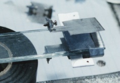 Begin by fastening the two 10" strips of glass together with a small piece of regular Scotch
tape across each end. There are two spacer flaps to be folded back flat on two of the feed capacitor plates in advance. Put double
sided Scotch tape on the inside surfaces of the feed capacitor plates. Place the plates about 1/16" from the end of the glass. Leave
the plates with the spark gap spread open at this time. The input connection has been folded and drilled with 1/16" drill for a #0-80
screw. The screw holds the input banana jack between the folded aluminum connection. Test fit the plugs before assembly. They
are added last using 2 nuts and 2 washers on each screw. The metal of the plugs is brittle and may not be drilled. Flatten it and
spread the hole slightly with an awl to allow the #0-80 to pass through. The red plugs on the front end are fastened temporarily with
hot melt glue as a strut. Position them to have the same distance between them as the black ones at the power input end (1 5/8").
The strut is then coated with Goop for strength.
Begin by fastening the two 10" strips of glass together with a small piece of regular Scotch
tape across each end. There are two spacer flaps to be folded back flat on two of the feed capacitor plates in advance. Put double
sided Scotch tape on the inside surfaces of the feed capacitor plates. Place the plates about 1/16" from the end of the glass. Leave
the plates with the spark gap spread open at this time. The input connection has been folded and drilled with 1/16" drill for a #0-80
screw. The screw holds the input banana jack between the folded aluminum connection. Test fit the plugs before assembly. They
are added last using 2 nuts and 2 washers on each screw. The metal of the plugs is brittle and may not be drilled. Flatten it and
spread the hole slightly with an awl to allow the #0-80 to pass through. The red plugs on the front end are fastened temporarily with
hot melt glue as a strut. Position them to have the same distance between them as the black ones at the power input end (1 5/8").
The strut is then coated with Goop for strength.
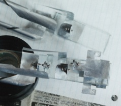 The output capacitor plates also have spacer flaps to be folded back flat in advance. Put
double sided tape on the outside of the output capacitor plates, on the outside of the supply capacitor plates and on the inside of the
spark gap arm of the supply capacitor. Preassemble the output capacitor and the supply capacitor on the glass spring bar. Put that
into place on the main glass base and into the feeder capacitor. Close the feeder capacitor plates down to the spring bar. The supply
capacitor plate should be mid way between the output capacitor and the feeder capacitor plates. The spring bar is what causes the
output capacitor to also serve as a socket for the antennas. The spacer flaps make aluminum at either end of the bar just a little bit
thicker so that the glass may be banded in the middle to serve as a clamp for the antenna jack. After assembly wrap a band of
electrical tape tightly around the middle of the spring bar. The piece of tape should be 12" long and 1/4" wide. Wrap it over the arm
of the spark gap from the feeder capacitor so that it is under the screw head.
The output capacitor plates also have spacer flaps to be folded back flat in advance. Put
double sided tape on the outside of the output capacitor plates, on the outside of the supply capacitor plates and on the inside of the
spark gap arm of the supply capacitor. Preassemble the output capacitor and the supply capacitor on the glass spring bar. Put that
into place on the main glass base and into the feeder capacitor. Close the feeder capacitor plates down to the spring bar. The supply
capacitor plate should be mid way between the output capacitor and the feeder capacitor plates. The spring bar is what causes the
output capacitor to also serve as a socket for the antennas. The spacer flaps make aluminum at either end of the bar just a little bit
thicker so that the glass may be banded in the middle to serve as a clamp for the antenna jack. After assembly wrap a band of
electrical tape tightly around the middle of the spring bar. The piece of tape should be 12" long and 1/4" wide. Wrap it over the arm
of the spark gap from the feeder capacitor so that it is under the screw head.
 Place the capacitor island at the other end. Put it equally between the spark gap points that
go to it. Secure the end of the longest coil last. Do one side first then flip it over and do the other side. With the points preset to
mid position they should line up with the tips of the points touching across the gaps as they are assembled. Support stands are
needed during construction. Two rolls of electrical tape for each end works well.
Place the capacitor island at the other end. Put it equally between the spark gap points that
go to it. Secure the end of the longest coil last. Do one side first then flip it over and do the other side. With the points preset to
mid position they should line up with the tips of the points touching across the gaps as they are assembled. Support stands are
needed during construction. Two rolls of electrical tape for each end works well.
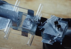
 The other end of the assembly is held in place by a 1" square of glass. The foot of the coil
is under the upper right corner of the glass square. The triangular spacer is under the lower left corner of the square. The lower left
corner of the square is brought in contact with the main glass base. A large blob of Goop is put on the lower left corner and around
the edge of the main base. Let that blob dry completely before wrapping a strip of electrical tape around left end of the squares.
This forms a crude clamp to hold the foot of the coil to the main base. The foot has double sided tape on both sides. Small strips of
glass (3/16" x 1") are placed with glue in the middle of each spark gap as platforms for the glass tubes to be installed next.
The other end of the assembly is held in place by a 1" square of glass. The foot of the coil
is under the upper right corner of the glass square. The triangular spacer is under the lower left corner of the square. The lower left
corner of the square is brought in contact with the main glass base. A large blob of Goop is put on the lower left corner and around
the edge of the main base. Let that blob dry completely before wrapping a strip of electrical tape around left end of the squares.
This forms a crude clamp to hold the foot of the coil to the main base. The foot has double sided tape on both sides. Small strips of
glass (3/16" x 1") are placed with glue in the middle of each spark gap as platforms for the glass tubes to be installed next.
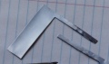
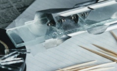
![]() The glass tubes are from automotive fuses.
Disassemble them with a soldering gun and scrub them clean with steel wool. Cut a notch in the ends of the glass tubes to fit around
the spark gaps. Use a mototool wafer stone to cut the glass. The fit does not have to be exact. Trimming of the outside of the tube
may be needed for some of them to fit into place. Gaps will be closed later with a coat of Goop. If the Goop gets inside the spark
gap area you will need a clean out tool made from coat hanger (left photo). The end of the clean out tool has a sharp edge. The
shape of the end has two points that are formed by the hollow cut of the edge. There are two gap gages made from aluminum stock
(center photo). The exact thickness is not important. The ratio of the thicknesses is. The tip of one of them is two thicknesses of
aluminum. This will be for the .50 gap (˝ of the arc size). The tip of the other is three thicknesses. It is for the .75 gap (3/4 of the
arc size). 1.0 is the size of a gap for the full voltage to be able to cause an arc. Set the finished gaps using a continuity checker
across each point being set.
The glass tubes are from automotive fuses.
Disassemble them with a soldering gun and scrub them clean with steel wool. Cut a notch in the ends of the glass tubes to fit around
the spark gaps. Use a mototool wafer stone to cut the glass. The fit does not have to be exact. Trimming of the outside of the tube
may be needed for some of them to fit into place. Gaps will be closed later with a coat of Goop. If the Goop gets inside the spark
gap area you will need a clean out tool made from coat hanger (left photo). The end of the clean out tool has a sharp edge. The
shape of the end has two points that are formed by the hollow cut of the edge. There are two gap gages made from aluminum stock
(center photo). The exact thickness is not important. The ratio of the thicknesses is. The tip of one of them is two thicknesses of
aluminum. This will be for the .50 gap (˝ of the arc size). The tip of the other is three thicknesses. It is for the .75 gap (3/4 of the
arc size). 1.0 is the size of a gap for the full voltage to be able to cause an arc. Set the finished gaps using a continuity checker
across each point being set.